Initial situation
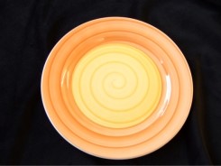
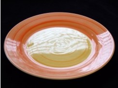
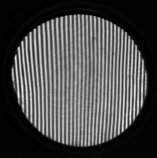
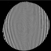
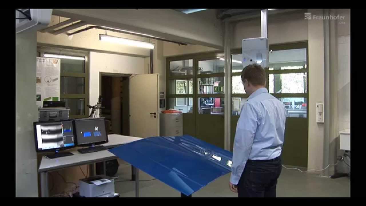
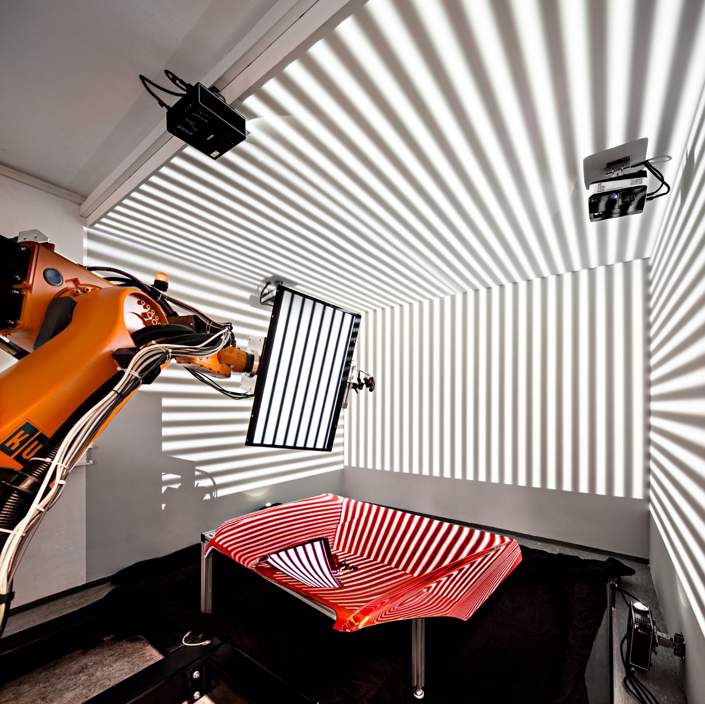
When inspecting specular surfaces, in contrast to diffuse reflection, an observer does not see the surface itself, but the mirror image of the surroundings. This causes considerable problems for the usual methods for determining the 3D object shape - such as triangulation or shape from shading - because they rely on at least partial diffuse reflection. The deflectometric measurement method, on the other hand, uses specular reflection: mirror images of known patterns in the surface and their deformations are observed. This procedure corresponds in principle to the inspection by the human observer who holds the surface to be inspected “in the right light“ and looks for disturbances in the mirror image.
Targets
This approach, which is intuitively mastered by humans, does, however, pose some challenges in terms of technical implementation:
When using commercially available LC displays as pattern generators, only small areas can be inspected in one measurement. It is therefore necessary to combine the deflectometric measuring device with a handling system to observe the test object from any position in space.
The quantitative reconstruction of specular surfaces represents an ill-posed inverse problem, for the solution of which additional information is required. Such additional information is obtained, for example, by means of localisation of a reference point, by means of several measurements from different camera perspectives or by sensor fusion with Shape from Shading data. The true 3-D reconstruction of the surface is computationally intensive and often not possible in real time. In practice, however, a reconstruction is often not even necessary if it is only important to determine the flawlessness of the test object. Here, inspection strategies with so-called "inverse" excitation are suitable, in which a defect-free object generates inconspicuous sensor data that can be evaluated very quickly.
Problem solution
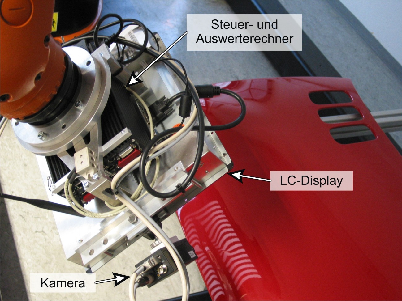
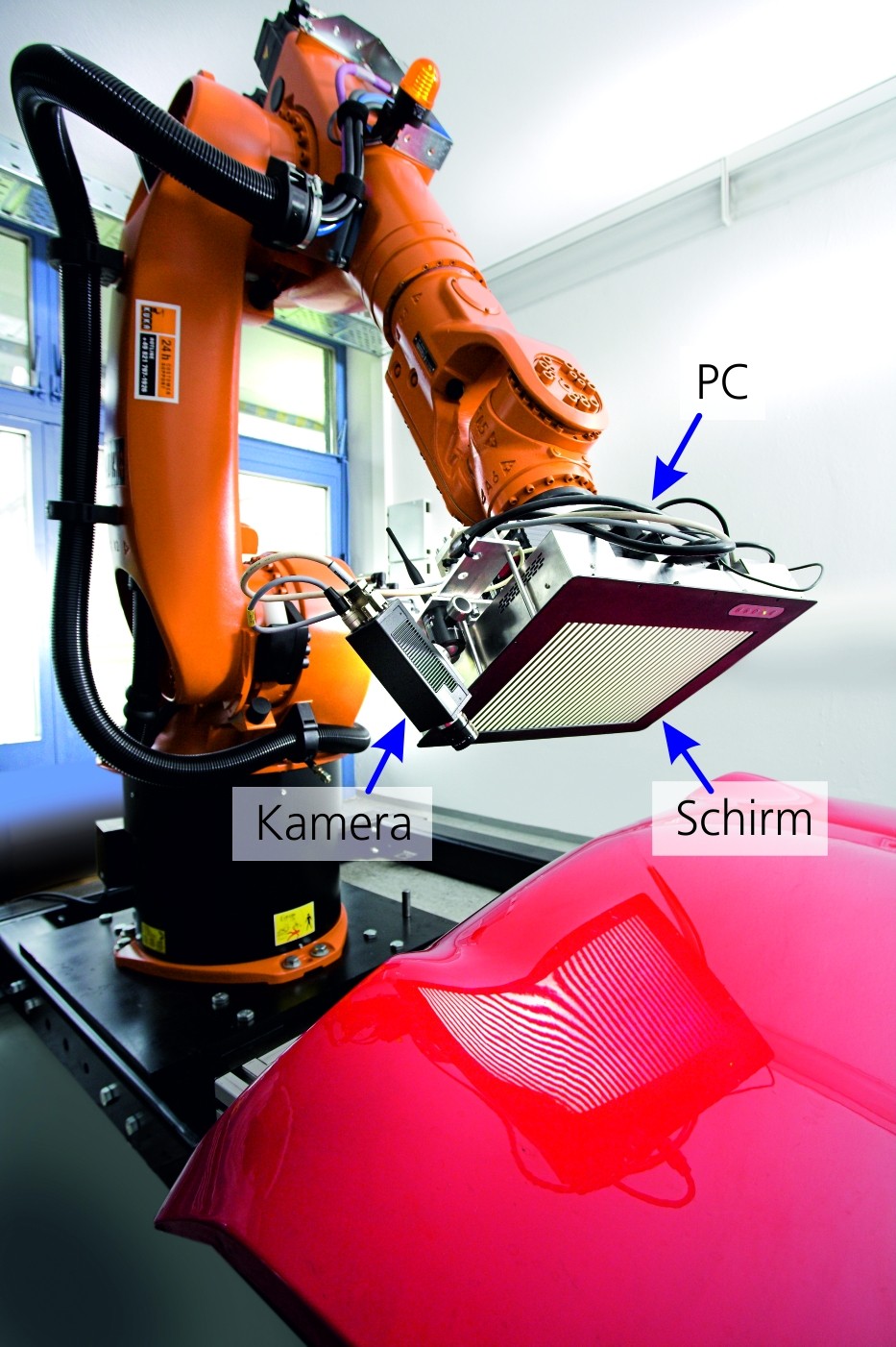
A robot-guided sensor head was developed at the Chair of Interactive Real-Time Systems in cooperation with Fraunhofer IOSB. The sensor head consists of an LC display as a pattern generator, several high-resolution video cameras and a sensor-integrated control and evaluation computer. The compact design of the sensor head allows it to be mounted on an industrial robot (see illustration above right).
Two approaches have been prototyped so far for reconstructing the reflective surface: Firstly, the targeted displacement of the sensor head during the measurement generates characteristic pattern variations, which is used to regularise the reconstruction problem. On the other hand, a novel method of sensor fusion has been developed for partially reflecting surfaces, which combines deflectometric measurement with a shape-from-shading approach.
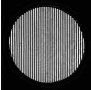
For the rapid inspection of known surfaces, a method based on inverse patterns was developed. For this purpose, deformed patterns are shown on the LC display, whose reflection in the surface results in undistorted camera images. The inverse patterns are generated in a calibration step on a defect-free specimen and are then available for series inspection.
In summary, deflectometry is an adequate measurement method for the inspection of reflective surfaces. It offers interesting perspectives in industrial use:
- High-precision inspection for the detection of the smallest defects,
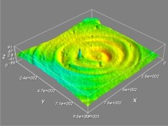
- complete reconstruction of the 3-D shape of the test object as well as
- rapid inspection using inverse patterns.